Glass Melting Furnaces
The type of furnace for melting glass typically depends on the type and quantity of glass being produced, and the local fuel and utility costs. While there are exceptions, the following discussion describes the primary furnace types and the glass segments that most commonly use each style.
There are two types of glass melting furnaces: Pot furnaces and Tank furnaces.
Pot Furnaces are structures built of refractory materials in which there is no contact between the furnace and the glass. Glass is melted in several pots made of refractory materials which are resistant to glass attack at high temperatures. The pots are charged with a batch, which is melted over a number of hours and worked on a 24 or 18 hour cycle. An average pot can hold 600-700 kg of glass. Pot furnaces are used where the glass is formed by hand and mouth blowing. One of the main advantages of this system is that several types of glasses can be melted at the same time. A pot can be used for about 30 melting cycles and thus produce between 18 and 21 tonnes of glass.
Fuel economy is normally achieved by recuperation, i.e., the pre-heating of combustion air by waste heat from the furnace exhaust gases. In this system the pre-heating of the combustion air is done by passing the air through metal tubes on the outside of which the exhaust gases flow towards the chimney. Thus the heat exchange is continuous. Electricity can also be used for melting.
Tank furnaces
Tank Furnaces are used where continuous flow of glass is needed to feed automatic glass forming machines. They are more economical in their use of fuel and are used mainly for the large scale production of containers, flat glass, electric bulbs, tubing and domestic machine made tableware. A large float glass furnace can have a capacity of 2,000 tonnes.
A tank furnace consists of a bath, built of a very special high refractory material, which can resist chemical attack of molten glass at temperatures in excess of 1500°C and a superstructure where combustion takes place. The quality of refractory materials, used for building the bath, has improved to such an extent that whereas some 30 years ago, the life of a furnace was well below 2 years, it is now over 9 years.
In order to achieve high melting temperatures and fuel economy, a regenerative or recuperative system is used. Both these systems utilise the waste heat of combustion for pre-heating the incoming combustion air.
While in the recuperative system the heat exchange between the combustion air and waste gases is continuous, in the regenerative system the waste gases are passed through a large chamber packed with refractory bricks arranged in a pattern which permits free flow of the gases. The brickwork is heated by the waste gases and after having been heated for some minutes, the direction of firing is reversed. Combustion air is passed through the chamber and the heat thus collected in the brickwork is used for pre-heating the combustion air. The firing is thus from right to left, during which time the right hand generator is heated and so there is a reversal of firing every x minutes. The cycle time can be changed for best heat exchange results and modern furnaces have computer managed control systems, which adjust the time of firing in each direction to achieve the best heat exchange conditions.
Heavy fuel oil or natural gas is normally used for firing tank furnaces. Glass, being an electrical conductor at high temperature, can also be melted by electricity. However, electricity is far too expensive and is normally used to boost the output from a gas or oil fired furnace. Nevertheless, technological progress in electric melting has enabled the use of all electric glass melting furnaces even at the high cost of electricity.
Unit melter
The term unit melter is generally given to any fuel-fired glass-melting furnace that has no heat recovery device. Generally, one is referring to an air/fuel-fired furnace when using this furnace term. However, most full oxy/fuel furnaces have no heat recovery system and are therefore, technically unit melters. Typically, the air/fuel unit melters are relatively small in size and are fired with 2 to 16 burners. Furnaces range in production from as large as 36 t of glass per day to as small as 230 kg of glass per day. Larger air/fuel unit melters are found in areas where fuel is extremely cheap. Frit, tableware, opthamalic glass, fiberglass, and specialty glasses with highly volatile and corrosive components are produced in unit melters. Due to the very low energy efficiency and the use of individual burners, the air/fuel unit melters are very amenable to oxygen-enhanced combustion techniques, including supplemental oxy/fuel boosting, premixed oxygen enrichment, and full oxy/fuel combustion. Oxy/fuel unit melters have been built as large as 320 t per day of glass to as small as 230 kg of glass per day.
Recuperative melter
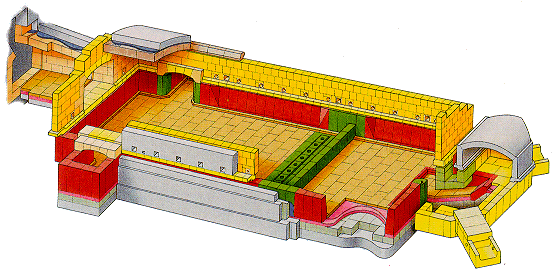
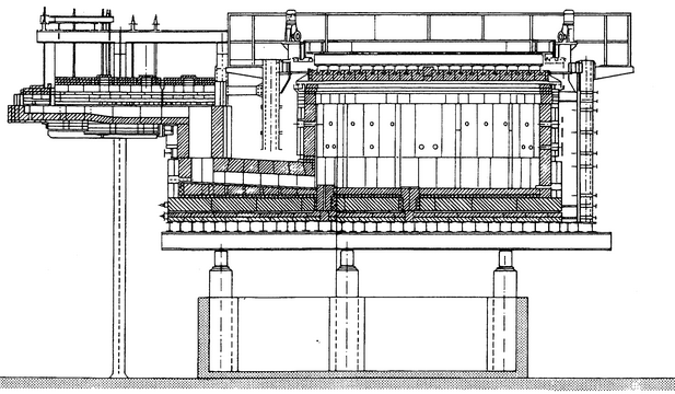
A recuperative melter is a unit melter equipped with a recuperator. Typically, the recuperator is a metallic shell-and-tube-style heat exchanger that preheats the combustion air to 540 to 760°C. The furnace is fired with 4 to 20 individual burners. These furnaces range in size from as large as 250 t per day of glass to as small as 18 t per day of glass. These furnaces are common in fiberglass production but can also be used to produce frit. Some recuperative furnaces are used in the container industry, though this is not common. Furnace life is a function of glass type being produced. For example, a 6-year furnace life is typical for wool fiberglass. A typical recuperative melter is shown in the following figure.

Chart 1: Typical recuperative melter (side view)
The recuperative melter is amenable to supplemental oxy/fuel technique or the premixed oxygen enrichment technique. Oxygen lancing is typically not used. In the supplemental oxy/fuel technique, an air/fuel burner is simply replaced by an oxy/fuel burner. When premix is applied, oxygen injection into the air main typically occurs downstream of the recuperator to avoid problems associated with air leaks in the recuperator. Care should be taken in locating the oxygen diffuser.
These furnaces are good candidates for full oxy/fuel. Recuperative heat exchanger efficiencies are much lower than with regenerative furnaces, and therefore fuel savings can help to drive the conversion. Also, recuperative furnaces operate in a continuous and steady firing mode of operation similar to oxy/fuel furnaces.
All-electric melter
As the name implies, all-electric melters receive all of the energy for glass melting through electrical heating. Electric current is passed through the glass by means of electrodes. Because of the electrical resistance of the glass, the glass is heated by Joulean heating. Electrodes are typically made of molybdenum; however, tin oxide, platinum, graphite, and iron have also been used. The electrodes are usually rod-or plate-type and can be located in the melter side walls or bottom.
The refractory tends to degrade much faster in these furnaces, resulting in very short furnace campaigns, typically less than 2 years. Most of these furnaces are less than 36 t of glass per day; however, furnaces as large as 180 t per day have been built. A typical electric melter is shown in figure below.
Due to the design of these furnaces, there is typically no fit for oxygen-enriched combustion. One exception is “hot top” melters which provide some heat via burners located above the bath. In this latter case, supplemental oxy/fuel or premixed oxygen enrichment has been practiced.

Chart 2: Typical electric melter
Regenerative or Siemens furnace
The regenerative furnace was patented in the U.S. by Siemens Corporation in the late 19th century. While some design evolution has occurred, the basic concept has remained unchanged. In a regenerative furnace, air for combustion is preheated by being passed over hot regenerator bricks, typically called checkers. This heated air then enters an inlet port to the furnace. By using one or more burners, fuel is injected at the port opening, mixes with the air, and burns over the surface of the glass. Products of combustion exhaust out of the furnace through a nonfiring port and pass through a second set of checkers, thereby heating them. After a period of 15 to 30 min, a reversing valve changes the flow and the combustion air is passed over the hot checkers that were previously on the exhaust side of the process. The fuel injection system also reverses. After reversing, the exhaust gases pass through and heat the checkers that had previously heated the combustion air.
The Siemens furnace is the workhorse of the glass industry. Most flat glass and container glass are produced in this furnace type. Regenerative furnaces are also used in the production of TV products, tableware, lighting products, and sodium silicates. There are two common variants of the Siemens furnace: the side-port regenerative melter, and the end-port regenerative melter.
End-Port Regenerative Furnace
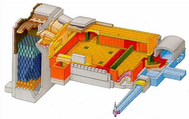
End-port regenerative furnaces are typically used for producing less than 230 t of glass per day. In an end-port furnace, the ports are located on the furnace back wall. Batch is charged into the furnace near the back wall on one or both of the side walls. The following figure shows the layout of a typical end port furnace. These furnaces are commonly used for producing container glass, but are also used for producing tableware and sodium silicates. For container production, a furnace campaign typically lasts 8 years.
Undershot of oxygen through lances and supplemental oxy/fuel have been used successfully on this type of furnace. Oxygen enrichment of the preheated combustion air has also been used on furnaces with damaged checkers.

Chart 3: Typical end-port regenerative furnace
Side-Port Regenerative Furnace
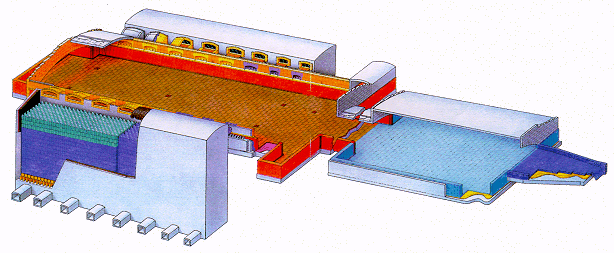
Side-port regenerative furnaces have ports located on the furnace side walls. Batch is charged into the furnace from the back wall. The next figure shows the layout of a typical side-port furnace. Side-port regenerative furnaces are typically used for producing greater than 230 t of glass per day. A side-port furnace for float glass commonly produces 460 to 630 t of glass per day. For container glass, side-port furnaces ordinarily produce between 230 to 320 t of glass per day. These furnaces are commonly used in container and float glass production, but are also used for the production of tableware and sodium silicates. For container production, a furnace campaign typically lasts 8 years and for float glass production can last as long as 12 years.
Undershot and supplemental oxy/fuel oxygen enrichment have been successfully used on this type of furnace. Premix enrichment has also been used on furnaces with damaged checkers. These furnaces have also been converted to full oxy/fuel.

Chart 4: Typical side-port regenerative furnace (Flat glass)

